
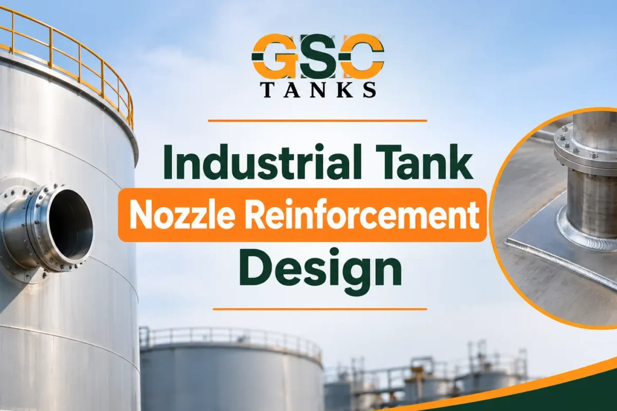
Industrial storage tanks use nozzles to connect process piping, pumps, valves, instruments, and other equipment. However, every nozzle opening changes the structural continuity of the tank shell. Therefore, engineers must evaluate the opening and provide adequate reinforcement to maintain structural integrity.
Nozzle reinforcement replaces the material removed when engineers cut an opening into a tank shell. It also helps the connection withstand the applicable design loads. Depending on the tank design, engineers may use additional shell thickness, nozzle neck material, a reinforcement pad, or a thickened insert plate.
Moreover, proper nozzle reinforcement helps reduce localized stress, deformation, and potential leakage. Consequently, engineers must consider reinforcement during the initial tank design rather than treating it as a simple fabrication detail.
This article examines the engineering principles, reinforcement methods, design calculations, external loads, and fabrication considerations involved in industrial tank nozzle reinforcement.
What Is Nozzle Reinforcement in Industrial Storage Tanks?
Nozzle reinforcement is a structural design provision that compensates for material removed from a tank shell during nozzle installation.
When a fabricator cuts an opening into a cylindrical tank shell, the opening interrupts the original load-carrying section. As a result, the surrounding material must carry the redistributed stresses.
For welded atmospheric storage tanks designed under API 650, engineers evaluate the reinforcement area around applicable shell openings. The required reinforcement must satisfy the standard’s area-replacement and welding provisions.
The reinforcement can come from several sources:
- Excess thickness in the surrounding shell plate.
- The available wall thickness of the nozzle neck.
- An additional reinforcement plate.
- A thickened insert plate.
However, not every nozzle requires a separate reinforcement pad. Engineers must first calculate the available reinforcement area and compare it with the required area.
Why Nozzle Reinforcement Matters in Tank Design
Nozzle openings create local changes in shell geometry and stiffness. Therefore, engineers must evaluate how these changes affect the tank structure.
Several engineering factors make nozzle reinforcement important.
1. Localized Stress Concentration
A nozzle opening interrupts the continuous structure of the tank shell. Consequently, stresses become concentrated around the opening.
The effect depends on the opening diameter, shell thickness, nozzle geometry, material properties, and applied loads.
Proper reinforcement helps distribute these stresses across a suitable area.
2. Loss of Shell Material
Cutting an opening removes material that would otherwise contribute to the shell’s strength.
Therefore, engineers must determine the amount of material removed and provide sufficient replacement area where the applicable design standard requires it.
3. External Piping Loads
Connected piping can transfer forces and bending moments to the tank nozzle.
For example, thermal expansion, pipe misalignment, equipment movement, and inadequate piping support can create additional loads.
As a result, engineers must evaluate the nozzle connection and surrounding shell for these loads.
4. Structural Deformation
Inadequate reinforcement can contribute to local shell deformation.
Furthermore, excessive piping loads can increase nozzle rotation and shell distortion. These effects may damage connections, welds, or attached piping.
5. Leakage Prevention
A poorly designed nozzle connection can develop excessive stresses or weld-related defects.
Therefore, engineers must combine proper reinforcement design with suitable fabrication, welding, and inspection practices.
Types of Industrial Tank Nozzle Reinforcement
Engineers can use different reinforcement arrangements depending on the tank geometry, shell thickness, nozzle size, material, and applicable design standard.
1. Reinforcement Pad
A reinforcement pad is an additional plate installed around a nozzle opening.
Fabricators weld the pad to the tank shell and provide the required nozzle attachment details.
The pad increases the available reinforcement area. Therefore, engineers can use it when the existing shell and nozzle neck material do not provide sufficient area.
Engineers must consider:
- Pad thickness.
- Pad outside dimensions.
- Opening diameter.
- Available reinforcement area.
- Attachment weld requirements.
- Applicable corrosion allowance.
- Inspection and testing requirements.
The reinforcement pad must satisfy the dimensional and welding requirements of the governing design code.
2. Thickened Shell or Insert Plate
A thickened insert plate provides additional material around the nozzle opening.
Instead of relying only on a separate reinforcement pad, engineers use a thicker shell insert to provide the required reinforcement.
This arrangement can offer a practical solution for larger openings or specific tank configurations.
However, engineers must evaluate the insert dimensions, corner radii, plate thickness, weld spacing, and transition details.
3. Integral Reinforcement
An integrally reinforced arrangement uses additional material within the nozzle or surrounding connection geometry.
This approach can reduce the need for a separate reinforcement pad.
Nevertheless, engineers must verify the available reinforcement area and ensure that the complete connection meets the applicable design requirements.
4. Reinforcement Through Excess Shell Thickness
Sometimes, the selected shell plate already provides more thickness than the minimum required for the design.
In such cases, engineers may be able to use part of this excess material as reinforcement.
However, only the material within the code-defined effective reinforcement limits can contribute to the calculation.
Therefore, engineers should not assume that all excess shell thickness provides usable reinforcement.
Nozzle Reinforcement Calculations and Engineering Considerations
Accurate reinforcement calculations help engineers determine whether a nozzle connection has sufficient material around its opening.
For API 650 tanks, the reinforcement area calculation forms an important part of shell opening design.
1. Determine the Required Reinforcement Area
The first step involves determining the opening dimensions and the applicable shell thickness.
Under the API 650 area-replacement approach, the minimum required reinforcement area is based on the vertical diameter of the shell opening multiplied by the applicable shell plate thickness.
The basic relationship is:
Required Reinforcement Area = d × t
Where:
- d = Vertical diameter of the opening in the tank shell.
- t = Applicable shell plate thickness.
API 650 permits the use of the required shell thickness instead of nominal thickness when the engineer has established the maximum required thickness for all relevant design and hydrostatic test conditions.
Therefore, engineers must use the correct thickness basis for the applicable design case.
2. Calculate the Available Reinforcement Area
Next, engineers determine how much reinforcement the existing materials provide.
The available area may include:
- Excess shell plate thickness.
- Effective nozzle neck material.
- Additional reinforcement pad material.
- Other permitted reinforcement configurations.
However, engineers must follow the dimensional limits and material requirements of the applicable standard.
Material outside the permitted reinforcement zone cannot automatically contribute to the required area.
3. Compare Required and Available Areas
Engineers compare the total effective reinforcement area with the required reinforcement area.
The basic acceptance relationship is:
Available Reinforcement Area ≥ Required Reinforcement Area
If the available area meets the requirement, an additional reinforcement pad may not be necessary for the area-replacement check.
Otherwise, engineers must modify the design. They may increase the reinforcement pad dimensions, select a suitable insert plate, or revise the nozzle arrangement.
Importantly, satisfying this area calculation does not automatically establish the complete structural adequacy of the nozzle connection.
4. Evaluate Material Properties
The shell plate, nozzle neck, and reinforcement plate must have suitable material properties.
Engineers should review:
- Yield strength.
- Tensile strength.
- Allowable stress where applicable.
- Corrosion allowance.
- Design temperature.
- Material compatibility.
Additionally, differences in material strength can affect how much reinforcement area a component contributes under the governing code.
External Loads on Industrial Tank Nozzles
Area replacement is only one part of nozzle design. Engineers must also consider the forces and moments transmitted through connected piping.
These loads can affect the nozzle neck, reinforcement plate, shell, and surrounding welds.
Axial Forces
Axial forces act along the nozzle centerline.
They can develop from pressure thrust, piping restraint, or connected equipment.
Bending Moments
Bending moments develop when piping applies forces at a distance from the nozzle connection.
For example, a long unsupported pipe can transfer significant bending loads to the tank shell.
Shear Forces
Shear forces act perpendicular to the nozzle axis.
They can develop through pipe weight, equipment movement, and external mechanical loading.
Thermal Expansion Loads
Piping expands and contracts as operating temperatures change.
If the piping system restricts this movement, it can transfer additional forces and moments to the nozzle.
Consequently, engineers should evaluate piping flexibility, support locations, and nozzle orientation during the design stage.
For applicable API 650 tanks, Annex P provides a method for evaluating certain external loads on shell openings. Engineers must use the relevant provisions of the applicable edition.
Welding and Fabrication Requirements for Nozzle Reinforcement
A correctly calculated reinforcement arrangement still requires proper fabrication.
Welding quality directly affects the integrity of the nozzle-to-shell connection.
Therefore, fabricators and quality control teams must follow approved drawings, welding procedures, and inspection requirements.
Nozzle-to-Shell Welding
The nozzle neck must have suitable attachment welds.
The welding arrangement depends on the nozzle configuration, shell thickness, and applicable code requirements.
Engineers should specify the required weld size, joint preparation, and welding details.
Reinforcement Pad Welding
When a reinforcement pad is used, fabricators must follow the specified attachment weld configuration.
They should also maintain the required fit-up, alignment, and weld dimensions.
Where required by the governing standard, a telltale or vent hole provides a means to check the integrity of the pad-to-shell weld space.
Welding Procedure Qualification
The welding procedure must suit the selected materials and joint configuration.
Depending on the governing code, the fabrication team may need qualified welding procedures and qualified welders.
Relevant considerations include:
- Welding Procedure Specification (WPS).
- Procedure Qualification Record (PQR), where required.
- Welder qualification.
- Preheat and interpass temperature.
- Heat input control.
- Weld inspection.
Non-Destructive Examination
Inspection helps identify defects that visual examination alone may not reveal.
Depending on the joint and applicable requirements, inspection methods may include:
- Visual Testing (VT).
- Magnetic Particle Testing (MT).
- Liquid Penetrant Testing (PT).
- Ultrasonic Testing (UT).
- Radiographic Testing (RT).
The applicable design standard, project specification, and approved inspection plan determine the required examination method and acceptance criteria.
Common Nozzle Reinforcement Design Problems
Several design and fabrication issues can affect nozzle performance.
Understanding these problems helps engineering teams avoid unnecessary modifications and costly repairs.
1. Incorrect Reinforcement Area Calculation
Using the wrong opening dimensions or shell thickness can produce an incorrect reinforcement calculation.
Therefore, engineers must verify all design inputs before approving the nozzle arrangement.
2. Undersized Reinforcement Pads
A reinforcement pad that does not provide sufficient effective area may fail the applicable area-replacement check.
Moreover, engineers must consider the code-defined reinforcement limits rather than relying only on the pad’s overall dimensions.
3. Excessive External Piping Loads
Poor piping support or restricted thermal movement can transfer excessive loads to the nozzle.
Consequently, engineers should coordinate tank nozzle design with the piping layout and stress analysis.
4. Inadequate Weld Details
Incorrect weld dimensions, poor fit-up, or unsuitable welding procedures can reduce connection reliability.
Proper fabrication control and inspection help address these issues.
5. Incorrect Nozzle Placement
Nozzle locations can affect nearby shell openings, weld seams, and structural discontinuities.
Therefore, engineers should review nozzle spacing and orientation before finalizing tank fabrication drawings.
6. Ignoring Corrosion Allowance
Corrosion reduces the effective thickness of exposed materials over time.
Therefore, engineers must account for the applicable corrosion allowance when evaluating the design and long-term service conditions.
API 650 Requirements for Tank Nozzle Reinforcement
API 650 is an important design standard for vertical, cylindrical, aboveground, welded storage tanks.
It establishes requirements for tank materials, design, fabrication, erection, and inspection.
Its shell opening provisions address reinforcement, attachment welding, and related construction details.
Engineers should pay particular attention to the following areas:
- Shell opening dimensions.
- Required reinforcement area.
- Effective reinforcement limits.
- Nozzle neck material.
- Reinforcement plate dimensions.
- Weld spacing and attachment details.
- External loads on shell connections.
API 650 also distinguishes between different shell opening configurations. Therefore, engineers must select the applicable requirements for the specific nozzle arrangement.
The American Petroleum Institute published the 14th edition of API 650 in August 2025. Engineers should consult the current edition, including applicable addenda and errata, rather than relying on outdated design references.
For additional background, read our article on What Is API 650? Standard Storage Tank Design Explained.
You can also consult the official API 650 standard information for its scope and publication details.
Material Selection and Nozzle Reinforcement
Tank material selection also affects nozzle design and fabrication.
Different materials have different mechanical properties, corrosion resistance, and fabrication requirements.
For example, steel tanks use welded shell connections. However, FRP and polyethylene tanks require different reinforcement approaches because their material behavior and joining methods differ.
Steel Storage Tanks
Steel tanks commonly use welded nozzle connections.
Engineers evaluate shell thickness, nozzle neck dimensions, reinforcement plates, and external loads.
The applicable design standard determines the reinforcement requirements.
FRP Storage Tanks
FRP tanks use composite reinforcement rather than conventional welded steel reinforcement pads.
Engineers must consider laminate thickness, fiber orientation, resin compatibility, and the structural connection between the nozzle and tank wall.
The design must account for the tank’s chemical service and operating conditions.
Polyethylene Storage Tanks
Polyethylene tanks require special attention to material flexibility, creep, thermal expansion, and connection design.
Nozzle reinforcement must suit the tank’s manufacturing method and material behavior.
A welded steel reinforcement detail should not be transferred directly to an FRP or polyethylene tank.
For a broader comparison, explore our guide to Choosing the Best Industrial Storage Tank Material for Your Application.
Similarly, material and sustainability considerations can influence the selection of green steel tanks.
Engineering Checklist for Industrial Tank Nozzle Reinforcement
Before approving a nozzle design, engineering teams should review the following points:
- Confirm the tank design standard and applicable edition.
- Verify the nozzle opening diameter and orientation.
- Establish the required shell thickness.
- Calculate the required reinforcement area.
- Determine the effective reinforcement from existing materials.
- Check reinforcement pad or insert plate dimensions.
- Verify material properties and corrosion allowance.
- Evaluate external forces and bending moments.
- Review nozzle spacing and nearby shell welds.
- Approve the welding details and inspection requirements.
- Verify compliance with the applicable design and fabrication requirements.
This checklist supports the design review process. However, it does not replace a complete engineering calculation or code compliance assessment.
Frequently Asked Questions About Nozzle Reinforcement
1. Why do industrial storage tanks require nozzle reinforcement?
Tank shell openings remove material and interrupt the original load-carrying section. Nozzle reinforcement replaces the required material and helps maintain structural integrity under applicable design conditions.
2. Does every tank nozzle require a reinforcement pad?
No. A separate reinforcement pad is not always necessary. Existing shell thickness and nozzle neck material may provide sufficient reinforcement. Engineers must verify the available area against the applicable design requirements.
3. How do engineers calculate nozzle reinforcement area?
For applicable API 650 shell openings, engineers determine the required reinforcement area using the vertical opening dimension and the applicable shell plate thickness. They then calculate the effective reinforcement available from the shell, nozzle neck, and additional reinforcement components.
4. What is the purpose of a nozzle reinforcement pad?
A reinforcement pad provides additional material around a nozzle opening. It helps replace the shell material removed during cutting when the existing shell and nozzle neck do not provide sufficient reinforcement.
5. How do external piping loads affect tank nozzles?
Connected piping can transfer axial forces, shear forces, and bending moments to tank nozzles. These loads can create localized stresses and deformation. Therefore, engineers must evaluate external loads separately from the reinforcement area calculation.
6. Which standard covers nozzle reinforcement in welded storage tanks?
API 650 covers relevant shell opening reinforcement requirements for welded atmospheric storage tanks within its scope. Other tank types and pressure vessels may require different design standards.
Conclusion
Industrial tank nozzle reinforcement plays an important role in maintaining the structural integrity of welded storage tanks. However, successful nozzle design requires more than adding a reinforcement plate around an opening.
Engineers must evaluate the required reinforcement area, shell thickness, nozzle geometry, material properties, welding details, and external piping loads. Furthermore, they must follow the applicable design standard and verify the complete connection before fabrication.
By addressing these factors during the engineering stage, project teams can improve connection reliability, reduce fabrication problems, and support long-term tank performance.
GSC Tanks provides industrial storage tank solutions across multiple materials and applications. Contact the team to discuss your storage tank requirements and identify a suitable solution for your project.
